

How to Install and Adjust Your Projector
TL;DR
Properly positioning and adjusting your projector before using software guarantees a sharper, faster, and more reliable projection mapping result. You must securely mount the device, reset all internal image distortions, and use test patterns and lens shift to align your image physically. Finally, rely on professional digital connectors like SDI or DisplayPort and match your display frequencies to ensure optimal stability.
Positioning your projector correctly before making any software adjustments is the most critical step in a video mapping project. Relying entirely on software to fix a poor physical setup leads to distorted images, loss of sharpness, and added latency. This guide covers the practical methods to securely install, optically adjust, and perfectly connect your projection hardware.
👉 Want to map your perfectly adjusted projector in seconds? Download the HeavyM free trial and start creating immersive visuals without any coding skills!
How to Position and Secure Your Projector?
Projection and Installation Method
- Level the projection surface: Check horizontally and vertically using a spirit level or a sighting device/grid. Only measure from the floor if it is perfectly level; otherwise, rely on the sighting device.
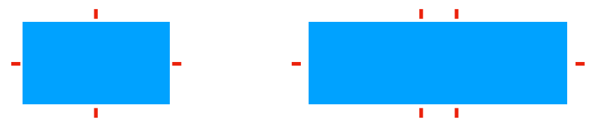
- Place discreet markers: Mark the horizontal and vertical midpoints with small pieces of matte tape. As an option, place two markers at the corners to check for orthogonality.
- Align the projector: Display a frame and grid pattern. Align the image with the center marks without using keystone (move the projector first, then shift the lens).
- Soft-edge (multi-projectors): Report the 10-20% overlap areas predicted by your simulation. Always place the blend away from high-contrast edges.
Standard Mounting Options
Check the manual for permitted installation types, maximum angles, ventilation clearance, and safety instructions. You can project from the front, use rear projection behind a screen, or mount it on a table or ceiling (flipping the image as needed). Follow the mounting diagrams regarding ceiling mounts, screws, and center distances.
Portrait/Edge Mounting: This is only possible if authorized by the manufacturer, primarily for cooling reasons. It is often specified as “360°/portrait OK” on certain laser models, but is less common on lamp models.
- Respect the authorized range (left or right) and tilt/temperature limits.
- Provide a portrait video input or use software rotation upstream (PC/software).
- Avoid forcing the keystone.
- When to use portrait mode: When the surface area is much taller than it is wide (columns, totems, narrow walls), or for vertical scenography displaying in 9:16 formats.
Essential Safety Precautions
- Ventilation & Cables: Leave the required clearance around ventilation grilles, clean the filters, and ensure a safe cable path with no traction on the connectors. Ensure hot air can escape; avoid closed boxes or recesses, as overheating leads to breakdowns and loss of brightness. Do not obstruct the unit with fabrics, adhesives, or objects.
- Secure Rigging: Follow the manual for approved anchor points and compatible screws/brackets. Mandatory safety slings are required (capacity must be ≥ weight of the projector + margin) with standard carabiners.
- Authorizations: Have the permissible load validated by a stage manager or rigger at the venue. No improvisation at height: use a basket/lifeline, and ensure personnel are trained and secured.
- Protected Perimeter: Use barriers or tape to prevent accidental impact or misalignment, and ensure no audience is seated directly under the unit.
Restoring Factory Settings and Physical Alignment
Before making any adjustments, restore the projector to its default settings (Menu > Reset → Restore factory settings and image).
- Disable all distortion: Check that Keystone = 0, Warp = OFF, and Angle correction = OFF.
- Neutral image mode: Select Cinema/sRGB, and turn HDR and enhancements OFF.
- Re-center the optics: Place the Lens shift in the center and the zoom in the middle of its range to maintain flexibility. Start with the focus near mid-travel.
Physical Alignment Steps:
- Flat: Set the projector perfectly level. If placed on a surface, keep leveling screws at a minimum. If rigged, use the mount’s leveling adjustments.
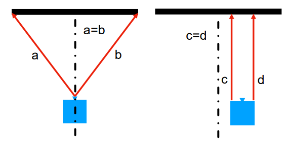
- Perpendicular & Centered: Align the optical axis facing the center of the screen.
- Rangefinder control: Verify that the distance from the optics to the left corner equals the distance to the right corner. If off-center, measure from the frame to compensate.
- Tip: Aim for perfect physical alignment before making any corrections. The better you adjust the projector physically, the more time you will save on video mapping alignment.
Test Patterns and Lens Shift
Displaying a Test Pattern
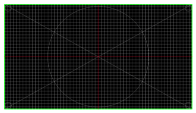
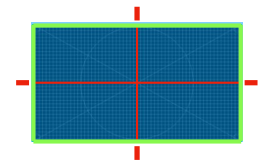
The adjustment test pattern allows you to finalize the placement of your projector. Your test pattern must have the same properties as the media you will be showing: resolution and aspect ratio. A good test pattern comprises:
- A visible green outline.
- Horizontal and vertical lines in red.
- A circle indicating a possible aspect ratio issue.
- Vertical and horizontal lines indicating that the focus will be uniform.
Note: For simple projections, such as on a screen with well-defined edges, the use of a dedicated test pattern is optional; you can adjust your projector directly using internal test patterns or media.
Centering the Image on the Projection Surface
The goal is to distribute the image over the surface without distorting it.
- Position the projector as centrally and perpendicularly as possible.
- Adjust the size with the ZOOM by aiming at the frame.
- Focus with the FOCUS in the center, then check the edges.
- Center the image using LENS SHIFT (horizontal/vertical), not keystone.
- If lens shift does not work, recheck the projector’s lateral/vertical placement.
- As a last resort, slightly adjust the projector, then recheck the geometry.
Best practices: Stay in the middle of the zoom range and lens shift. After each adjustment, repeat the process: zoom → focus → lens shift. Do this before any mapping/warping. Minimize the use of Keystone: use it only if no other solution is possible.
Analyzing Test Pattern Distortions
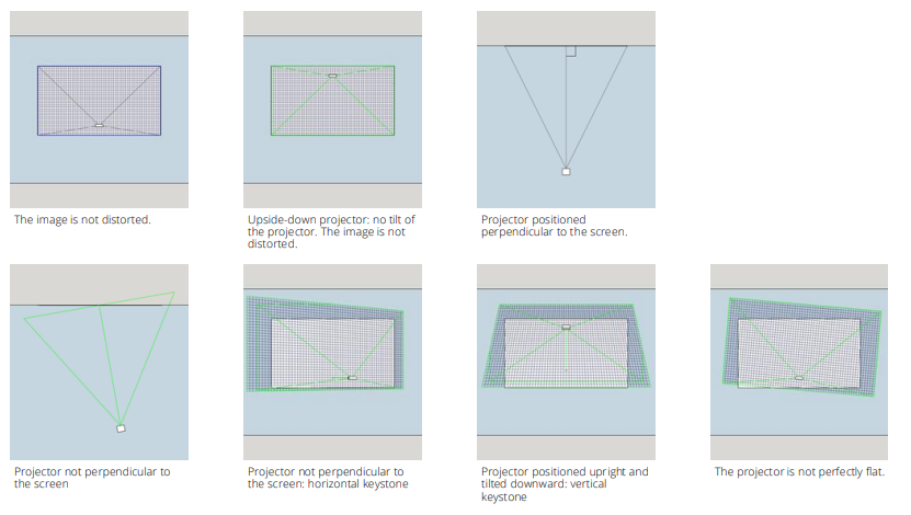
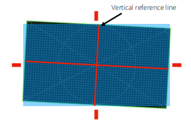
- Tilted vertical reference line: The test pattern is not straight in relation to the screen. Solution: Level the projector.
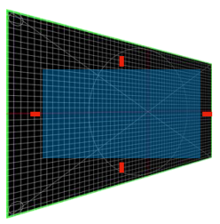
- Horizontal trapeze: The horizontal axis of the projector is not perpendicular to the screen. Solution: Rotate the projector.
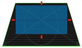
- Vertical trapeze: The vertical axis of the projector is not perpendicular to the screen. Solution: Rotate the projector.
Understanding Lens Shift
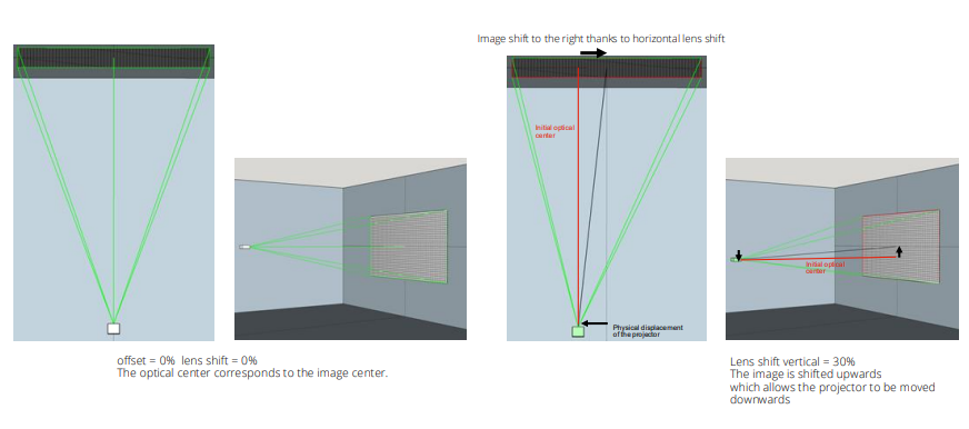
Lens shift is the physical movement of the optical block to shift the image vertically and/or horizontally without distortion (no trapezoidal distortion, no loss of sharpness). It is expressed as a percentage of the image around the center.
- Example: For an image 3.0 x 1.7 m with V=±60% and H=±30%, the maximum center displacement is ±1.02 m vertically and ±0.90 m horizontally.
- Best practices: Use lens shift first to center; stay in the middle of the range and avoid the stops, which can cause vignetting or aberrations.
- Limits: It does not correct angle or poor perspective. Short focal lengths or UST lenses often have little or no lens shift. Vertical and horizontal shifts are often linked (the more you push one, the less the other is available). Remember, not all projectors have a Lens Shift function.
Case Study: Calibration with a Special Test Pattern A special test pattern is created specifically for the projection surface, at exactly the same resolution. It is used to align the image with real landmarks (contours, doors, windows, roof) so content lines up perfectly. The objective is to minimize distortions and adjust warping with video mapping software. Avoid significant overall distortion and strong keystone; prefer dedicated surfaces/masks and minor local adjustments. Any distortion reduces sharpness and may add latency. Proper positioning greatly limits these corrections.
👉 Need to draw precise masks on your building? HeavyM makes masking and warping incredibly simple. Try HeavyM today!
Fine Adjustments, White Balance, and Uniformity
Understanding Offset
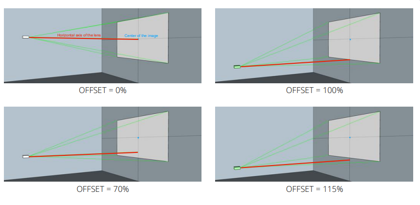
Offset is the fixed vertical distance between the optical axis of the projector and the center of the image. It is indicated as a percentage of half the image height (a value specific to the lens, not adjustable).
- Example: Image height 2.0 m, offset +60% → the center of the image is 0.6 × (2.0/2) = 0.60 m above the optical axis, so the bottom edge will be higher than the bottom of the projector.
- Why it’s key: It determines the position of the mount (table/ceiling) and avoids having to tilt (trapezoid). Two models with the same brightness may be incompatible for blending if their offsets differ. You can find it in the technical specifications, or perform a quick test to measure it before mounting.
The 3-Step Fine Adjustment Process
- Step 1 – Sharpness (1 min): Display the test pattern. Adjust the FOCUS first in the center, then check the corners. If one side is blurred, realign the projector (no software adjustment possible).
- Step 2 – White Balance (1 min): Open the Image menu and choose a neutral mode (Cinema/sRGB). Search Color temperature: if the image has a blue cast, reduce the Blue setting slightly. If the image appears yellow/red, reduce the red slightly. The objective is a neutral white on a blank screen.
- Step 3 – Uniformity (1 min): Display a gray screen, then a white screen. Check for any lighter areas or stains. Clean the lens and check the projector is facing the right way. If a corner is “burnt,” lower the Contrast slightly.
For Multi-projectors: Select one “master” projector whose color is OK. Align the others by eye so that they resemble the master (same white balance, same brightness).
Final check (30 s): Ensure the grid is straight and clear in the center and at the edges, white is white (not blue/yellow), and the gray/white is even (no lighter/darker areas).
4. Signals, Connections, and Connectors
The objective is to transmit a stable image at the correct resolution and frequency. Use digital connections and maintain the same frequency everywhere (e.g., 1920×1080 @60Hz).
The Main Video Connectors
| Connector | Characteristics | Pitfalls / Limits |
| HDMI (2.0/2.1) | Most common standard. Digital (signal is either good or absent). 4K60 requires HDMI 2.0 (18 Gbps); beyond that requires 2.1. Copper is reliable up to 10-15 m; use active cables/fiber or HDBaseT beyond. | HDCP may block certain sources. Fragile connector (secure with cable ties). |
| VGA (Blue) | Transmits an analog computer signal. Becoming obsolete. | Sensitive to electrical interference; signal deteriorates over long runs (ghosting). 50m max with good cable and low resolution. No 4K support. For troubleshooting only. |
| DisplayPort (DP 1.2/1.4) | Excellent from a PC: connector lock, multi-screen management. 4K60 without problems, 1.4 goes further (4K120 depending on bandwidth). Distances similar to HDMI. | Avoid unreliable passive dongles; use active adapters if converting DP to HDMI. |
| DVI | Old generation digital. DVI-D Dual Link up to 2560×1600@60. | Use only if this is the only available input. |
| Coaxial SDI (3G/6G/12G) | Standard broadcast: robust, lockable, long distances. 3G-SDI = 1080p60; 12G-SDI = 4K60 over ~50-70 m of professional coaxial cable. | Requires HDMI/DP to SDI converters on the PC side. |
| HDBaseT | Transports HDMI + controls over Cat6/7 Ethernet cable up to 70-100 m. 4K60 often limited to 40-70 m. Very low latency. | Uses a specific protocol not compatible with conventional networks. |
Other Transport Technologies:
- Fiber optic HDMI cable: Long distance (30-100m). Pay attention to the connection direction. Fiber is fragile and should not be bent.
- NDI (over IP): Ethernet network codec. Requires an NDI to HDMI/SDI decoder. Pay attention to network quality and image compression.
- Fiber optic connections: Covers several hundred meters with no perceptible loss or latency. Requires encoders and decoders.
Display Frequencies (50/60Hz)
Frequency is the number of images displayed per second (sometimes specified in the resolution, e.g., 4K60). If projectors, lights, and cameras are not at the same Hz, you will get rolling bands or flicker during recording.
- Rule: Choose a single frequency for the entire chain.
- In Europe: output at 50Hz (25/50 fps content); Americas/JP: 60Hz (30/60 fps).
- Cameras: shutter speed 1/50 or 1/100 (50Hz) or 1/60 or 1/120 (60Hz).
- Checklist: test with the camera; if there are stripes, align everything to 50 or 60.
EDID and HDCP Management
EDID (Extended Display Identification Data): The identity sheet that a screen/projector sends to the PC. It contains supported resolutions, frequencies, timings, color spaces, and sometimes HDR/audio.
- Common issues: Screen not recognized, window jumps around, or desynchronization in multi-output mode (pulsing blending).
- Causes/Solutions: Projector turned on after the PC. Always turn on projectors/splitters first, then the PC, then the software. Avoid questionable cables; use certified active adapters and avoid daisy chaining. Force PC output (e.g., 1920×1080 @60Hz, Full RGB, HDR OFF, 100% scaling).
HDCP (High-bandwidth Digital Content Protection): Copy protection built into HDMI/DP/DVI signals (not SDI). If the entire chain is not HDCP-compatible, the image will not be displayed.
- Symptoms: Black, gray, blue screen, error message, or image appearing/disappearing.
- Causes: Playing a protected source (iTunes/Netflix, Blu-ray player, consumer box).
- Best practices: Use unprotected media (exported local files). Prefer direct PC output and professional HDCP-compliant devices. Avoid consumer streaming boxes for live events. If in doubt, switch to SDI for video transport.
👉 All set up? Now it’s time to map! Download HeavyM and bring your perfectly adjusted hardware to life.
Frequently Asked Questions (FAQ)
What is the difference between Lens Shift and Keystone? Lens shift is a physical movement of the optical block to shift the image vertically or horizontally without causing trapezoidal distortion or loss of sharpness. Keystone is a digital correction that should only be used as a last resort.
What is projector offset and why is it important? Offset is the fixed vertical distance between the optical axis of the projector and the center of the image. It determines the necessary height and tilt of your projector and is critical for blending multiple projectors, as two models with the same brightness may be incompatible if their offsets differ.
How do I fix a black or flashing screen on my projector? This is often an HDCP (copy protection) issue. If your source (like a Blu-ray or streaming box), converter, or cable is not HDCP-compliant, the image is blocked. Ensure you are playing unprotected media directly from a PC, or switch to SDI connections.
Why does my projection flicker on camera? Flicker and rolling bands happen when the display frequency (Hz) of the projector does not match the camera’s shutter speed. You must choose a single frequency (50Hz for Europe, 60Hz for the US) for your entire chain: PC, projectors, and cameras.
How do I clean up blurry edges on my projection? First, ensure the projector is perfectly perpendicular to the surface. Display a test pattern and adjust the focus in the center, then check the edges. If one side remains blurred, you must physically realign the projector, as no software adjustment can fix physical optical blur.